 EN
EN  ES
ES  PT
PT  FR
FR  RU
RU  KO
KO RESOURCE CENTER > CASE STUDIES
10‑Ton Dual Synchronised Tilter for Aerospace Defence|Switchable Sync/Independent Mode
RELATED MEDIA
SHARE







POSTED: 7/10/2026
Overview
Project Type: Heavy‑duty mechanical tilter (dual‑unit synchronised / independent switching)
Client: An aerospace defence technology research and test institution
Location: Beijing, China
Industry: Aerospace & defence (missile weapon system development and testing)
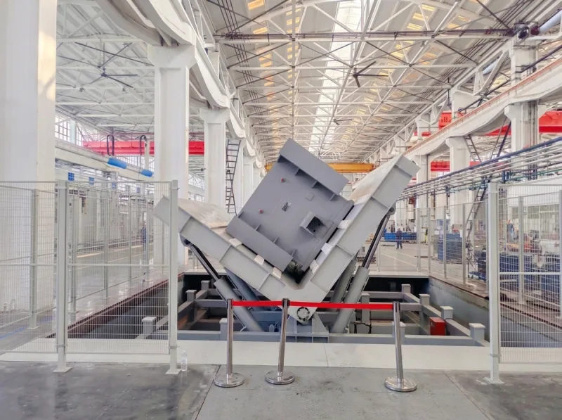
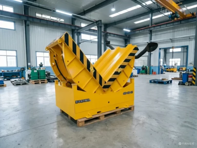
Core Function: 90° vertical tilting of large products for environmental and reliability testing
Key Parameters: 10‑ton capacity, 90° tilt angle, 7‑metre dual‑unit spacing, synchronised/independent dual‑mode switching, ~50‑second tilt cycle
Industry Context
The client is affiliated with a major aerospace defence group, responsible for developing national air defence missile weapon systems. It is a leading institution integrating scientific research, testing services, and technology development, specialising in component verification, environmental and reliability testing, materials analysis, and non‑destructive testing.
During the development of missile systems and aerospace products, large structural components, cabins, and system‑level products require multi‑angle environmental and reliability testing – products must be tilted 90° from horizontal to vertical to simulate actual service conditions for vibration, shock, temperature, and other tests.
Two major bottlenecks with traditional single‑unit tilters:
- Inconsistent tilt angles: Two independent units cannot guarantee synchronised tilting across both ends of a large product.
- Low test efficiency: Only one product can be processed at a time – unable to meet batch testing demand.
The client needed two 10‑ton tilters capable of both synchronised and independent operation, spaced 7 metres apart to accommodate large cabins and structural components.
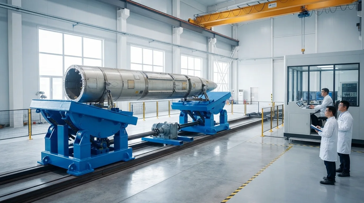
Basic Parameters
| Parameter | Specification |
|---|---|
| Equipment type | Heavy‑duty mechanical tilter |
| Quantity | 2 units |
| Rated load | 10,000 kg (each) |
| Tilt angle | 90° |
| Platform size | 1500×1000mm + 1000×1500mm |
| Tilt mechanism | Mechanical chain drive |
| Tilt speed | ~50 seconds / 90° |
| Dual‑unit spacing | 7,000 mm |
| Drive mode | Single‑motor synchronised / independent (switchable) |
| Mode switching | Quick drive‑shaft disconnect |
| Colour | Blue |
| Electrical system | Three‑phase four‑wire, Delixi components |
| Power cable | 6‑metre three‑phase four‑wire with plug (national standard) |
| Auxiliary features | Forklift fork entry points, crane lifting holes |
| Process requirements | Reinforced clean welds, neat cable routing |
Solutions
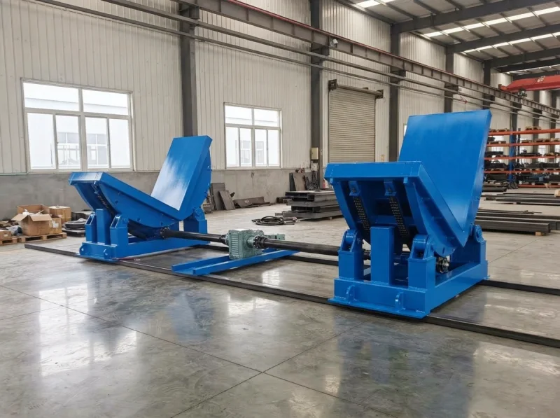
Dual‑unit synchronised drive system – one motor drives two tilters
Design approach: Two tilters spaced 7 metres apart are connected via a central motor with couplings. The motor simultaneously drives both units for synchronised tilting – ensuring perfect angle consistency across both ends of a large cabin. This is critical for precision aerospace products, where any angle deviation would compromise test data reliability.
Independent mode: Removing the drive shaft connection on one side allows each tilter to operate independently.
Drive scheme: A single motor connects to both tilters via drive shafts and couplings. In synchronised mode, motor torque is transmitted to both units simultaneously; in independent mode, one coupling is disconnected, driving only a single unit.
Quick disconnect & re‑engagement mechanism – easy mode switching
Operation: Switching to independent mode simply requires removing the shaft connecting the motor to one tilter. Once removed, each unit operates independently. Reconnecting the shaft restores synchronised mode.
Precision assurance: The drive shaft uses keyed connections + dowel pins, ensuring coaxial alignment between shaft and coupling even after repeated removal and re‑installation – maintaining angle consistency in synchronised mode.
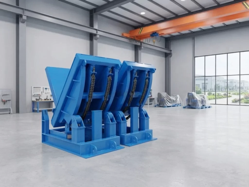
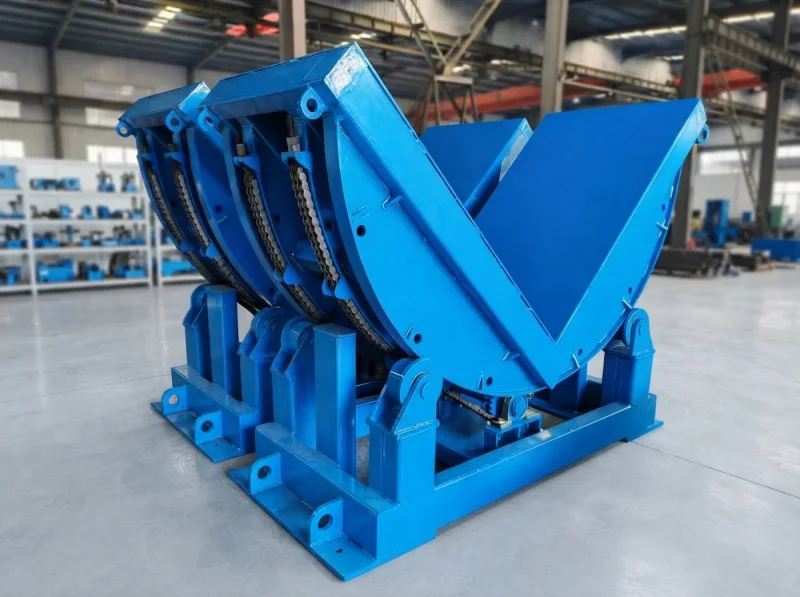
10‑ton heavy‑duty structural design
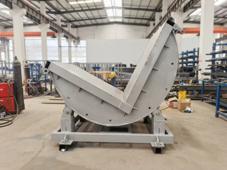
- Tilt mechanism: Mechanical chain drive (non‑hydraulic) – impact‑resistant, leak‑free, ideal for defence applications
- Platform size: 1500×1000mm + 1000×1500mm (dual platforms, tilt axis along short side)
- Tilt speed: Approximately 50 seconds for 90° tilt
- Tilt angle: 90° (horizontal → vertical)
- Operational convenience: Reserved forklift fork entry points and crane lifting holes
Defence‑grade process standards
- Welding: Reinforced, visually clean welds – defence projects demand high weld quality and appearance
- Electrical: Three‑phase four‑wire control cabinet with earth terminal, Delixi components; neatly routed internal wiring, all signal cables in ducts
- Power cable: 6‑metre three‑phase four‑wire cable with plug (national standard)
- Colour: Blue
Urgent delivery
Ordered on December 16, shipped on December 31 – just 15 days. Priority production scheduling with key components pre‑stocked to ensure on‑time delivery.
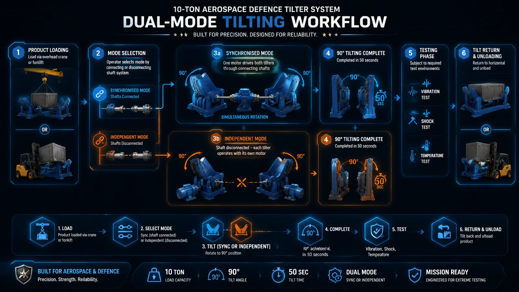
Workflow
Step 1: Mode selection – Choose synchronised or independent mode based on test requirements. Synchronised: install drive shaft connecting both tilters; independent: remove the shaft.
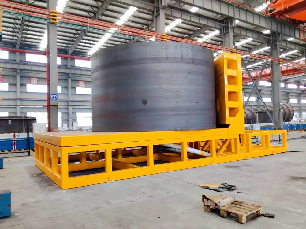
Step 2: Product loading – Use crane or forklift to place the large product (missile cabin, aerospace structure) onto the tilter platforms.
Step 3: 90° tilt – Start the motor. Both units (synchronised mode) or a single unit (independent mode) complete a smooth 90° tilt in approximately 50 seconds – product moves from horizontal to vertical.
Step 4: Test operation – Perform environmental and reliability tests (vibration, shock, temperature, etc.) in the vertical position.
Step 5: Tilt return – After testing, the units tilt back 90° to reset. Product unloaded, ready for the next cycle.
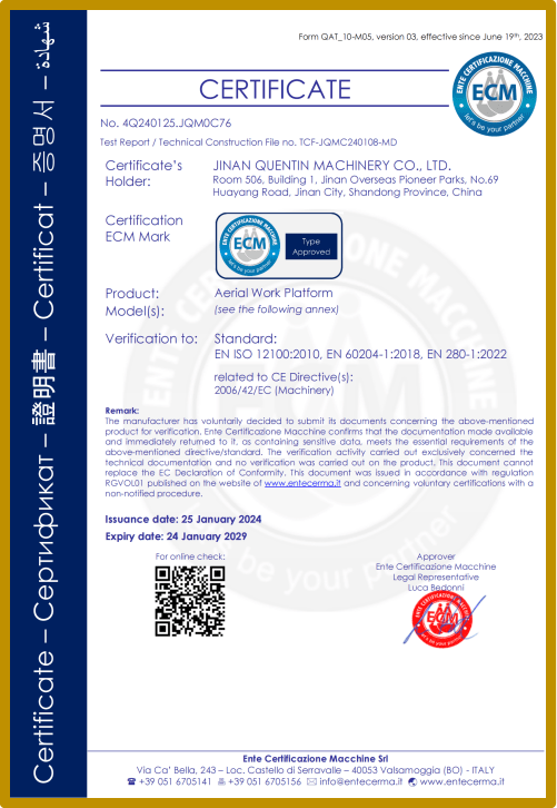
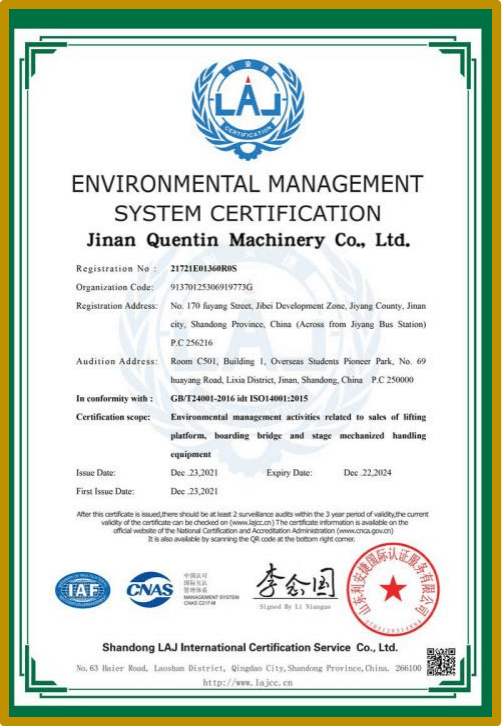
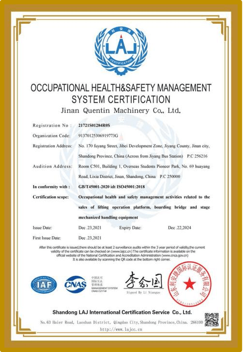
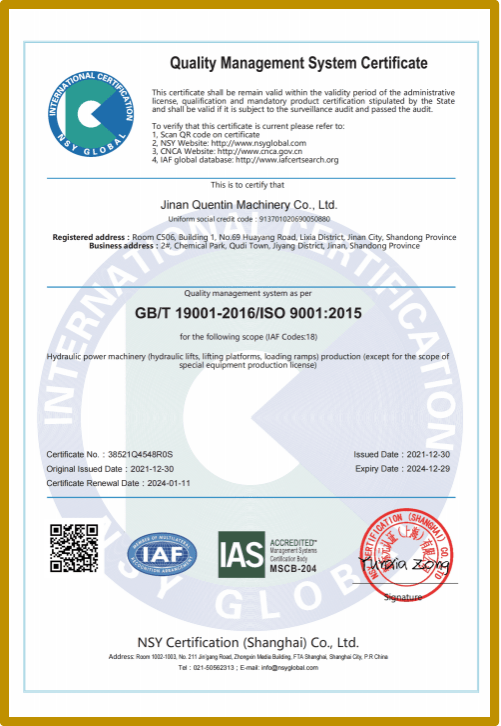
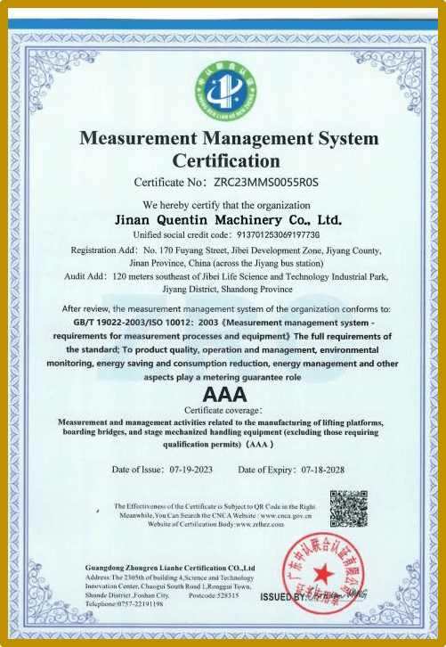
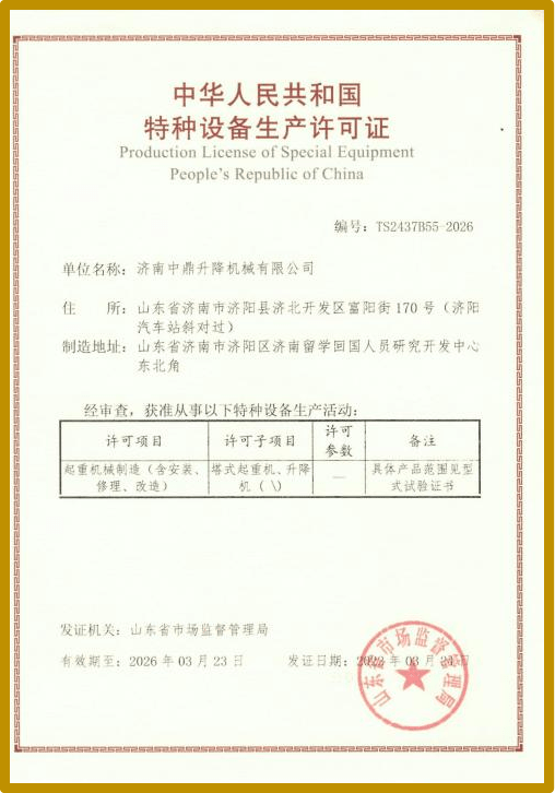
Product Certificates
FAQ
If you want to customize your material handling equipment, please contact us →.